Refurbishment of an old TONNA F9FT Antenna — 9 January 2021

Refurbishment of an old TONNA F9FT Antenna

In the early 2000’s I bought an F9FT 21 elements antenna. I used it during the golden age of packet radio and I enjoyed the beautiful performances of this yagi for establishing links across long distances. The datasheet and manual can be found here below.

When I moved out of my city for work, I uninstalled the antenna from the roof and I stored it without any maintenance. Recently, I needed this antenna for experimenting a link with New Packet Radio. I recovered the antenna from my garage and I found it in very bad conditions. Consider that the antenna was installed very near to the coast, so the sea salt increased the corrosion.

As you can see, the aluminum parts were full of oxide and the feeding point of the folded dipole was completely broken. I didn’t use more than 25Watts, so I think the plastic was broken due to atmospheric and thermal stress. The inox screws are still perfect, but the clamps are rusty.

I have been tempted to buy a new antenna, but the OM should be patient, should save money and love repairing so… let’s repair!

I started from the more boring job: cleaning the aluminum parts. I decided to avoid acids and use only WD-40 and an inox sponge.

It took about 2 hours but the results are good.

Then, I cleaned all the isolators with a brush and Chanteclair. I also cleaned the inox screws with WD-40:

Now it’s the turn of clamps. I used the circular metallic brush mounted on the drill, and a bench vise to hold the pieces during the operations and work in safety. Here below the pieces before the cleaning

And after the cure:

The final step is the painting with spray Zinc. I used the following, a good quality one:

The clamps looks like new after painting. I preferred to pur 2 coats of paint for a better results.

The last but very important operation is the restoration of the feeding point. I found the complete and original TONNA dipole as replacement part, but it’s not very cheap (about 30$ + shipment expenses). So I decided to build it by myself. I decided to use an ABS 10cmx10cm electric box, an SO-239 flange connector (I didn’t have N type in my drawers, but it would have been better…) and two brass electric terminals for contacting the aluminum elements, which are not weldable. The pictures below explains better my idea.

I installed and tested my antenna and it works perfectly. The ROS is 1.2:1 at 431 MHz. The resonance frequency is slightly shifted down compared to the design (432MHz), but the bandwidth is still good.

Here below some pictures of the installation.

73’s

Alfredo IZ7BOJ

APRS spam alarm by telegram notifications — 8 December 2020

APRS spam alarm by telegram notifications

In this article I described how all the aprs stations of my region are monitored on a dashaboard and how all the sysops are informed about downtimes of the Igate/digipeaters.

Here below, I’m going to describe another step for the local aprs situation awareness. Sometimes the sysops see stations transmitting a lot of unuseful beacons with excessive rate, both fixed or mobile ones. Wrong beacon intervals can congest the monitor frequency and increase packet collisions, so this issue is something we’re contiuously fighting woth. When one or more TX I-gates are part of the network, particular care must be taken for the smartphone apps like aprsdroid which sends a lot of beacon on the internet (APRS-IS) and then transmitted in RF by I-gates. More and more popular platform like MMDVM, PI-Star, DMR and C4FM contribute to the 144.800 congestion if they are not properly managed or filtered.

Most of the times, if the abnormal beacons are permanent, local sysops shall get in touch with these operators and explain why they’re doing spam and how to fix it, because they normally don’know very well how the APRS works and they don’t know how their packets are transmitted.

In order to identify as soon as possible these situations, I started to think to an automatic message system, based on telegram and similar to the vitality messages described in this article.

The requisites of the oftware are:

  1. Read logs of my aprx server
  2. Periodically check for spam stations in the log
  3. The spam rate shall be adjustable
  4. The check period shall be adjustable
  5. The notifications shall be sent by telegram

The solution was a simple python script based on telegram-send.

The script is available here: https://github.com/IZ7BOJ/aprs_station_monitor .

The script performs the following operations:
1) open aprx rf log file and takes the last ‘cycletime’ time interval;
2) for every stations heard, counts the number of beacons transmitted (excluding digipeated packets);
3) for every stations heard calculates the mean tx rate as: heard beacons / interval time;
4) if the rate is > ratelimit, the script sends telegram notification.

Note: the scripts calculates a mean beacon rate over the interval. Sometimes it can underestimates the rate, but I wanted to intercept only serious spam situations.

Installation and configuration

Dependencies: before using this script, intall and configure the library “telegram-send ( https://pypi.org/project/telegram-send/ ) and configure the destination of the notifications (single user, group or channel).

sudo pip3 install telegram-send

telegram-send –configure if you want to send to your account
telegram-send –configure-group to send to a group
telegram-send –configure-channel to send to a channel.

In the first part of the script, the following parameters shall be edited:

interface: radio interface (CALLSIGN) declared in aprx.conf
logfile: aprx rf log file (typically ‘/var/log/aprx/aprx-rf.log’)
telegram_conf_file: telegram_send config file (typically ‘/home/pi/.config/telegram-send.conf’)
cycletime: cycletime in seconds
ratelimit: max frames in a cycletime

The script should be executed every ‘cycletime’ by crontab. Here below, a typical crontab config for 10 minutes interval:

*/10 * * * * sudo /home/pi/Applications/aprs_spam_check/aprs_spam_check.py

Note: This script may have bugs and it’s written without all the best programming rules. But it works for me.

Here below, an example of spam notification is reported:

The script can be easily adapted to work with other logs, like direwolf or similar.

Any comment/suggestion will be appreciated.

73’s

Alfredo IZ7BOJ

Descrizione del mio setup di stazione mobile — 30 November 2020

Descrizione del mio setup di stazione mobile

Viaggiando molto, mi son trovato spesso a operare in mobile, prevalentemente in V/UHF.
Non volendo “violentare” la mia auto con la perforazione della cappotta e installazione di un’antenna fissa, ho sempre utilizzato antenne a base magnetica.
Se da un lato questo tipo di antenna è pratico da installare e lascia la macchina esteticamente “pulita” quando non è montata, di contro presenta lo svantaggio del passaggio del cavo, che rimane pendente nell’abitacolo ed è di intralcio soprattutto quando non si è soli in auto.
Volendo trovare una soluzione più gradevole e meno precaria, mi son messo a pensare come poter sistemare le cose in maniera un po’ più professionale.
I requisiti della mia stazione mobile sono questi:

  1. Utilizzo di antenna a base magnetica;
  2. Passaggio dei cavi quanto meno possibile penzolante e a vista;
  3. Utilizzo del FT2-D e posizionamento stabile sul cruscotto, con display a vista;
  4. Installazione di un amplificatore lineare V/UHF attivabile tramite switch e installato non a vista;
  5. Ascolto dell’audio in ricezione tramite impianto radio dell’auto;
  6. Sistema “vivavoce” in trasmissione.

Di seguito faccio vedere punto per punto quali soluzione ho adottato.

1) La base magnetica è di diametro 20cm, quindi stabile e sicura anche oltre i 100Km/h. L’antenna che ho sempre utilizzato è la diamond NR770R:

Il cavo è stato tagliato a misura giusto per entrare nell’abitacolo e all’estremità è stato installato un connettore SMA maschio. Più avanti faccio vedere quale soluzione ho adottato per arrivare alla radio.

2) Come si vede in figura, per limitare il penzolamento dei cavi, un coassiale a bassa perdita è stato infilato nel percorso tratteggiato blu, dalla radio fino al montante lato guidatore. In quel punto un connettore SMA femmina rimane esposto, e questo purtroppo è inevitabile.

3) Per l’installazione stabile del FT2-D, ho usato una staffa metallica che si aggrappa alle alette delle bocchette di areazione dell’auto. E’una staffa un po’ particolare che acquistai online un po’ anni fa, ma di cui non riesco a trovare i riferimenti. Mi son sempre trovato molto bene e all’occorrenza si può togliere facilmente, perchè si regge con delle clips elastiche. Allo stesso tempo è stabile e ha sempre retto senza problemi un Kenwood TH-D72 e ora un FT-2D.

4) Il lineare che ho scelto è il seguente.

Ha il vantaggio di avere la selezione automatica della banda V/UHF tramite sensing a radiofrequeza, quindi l’ho installato lato passeggero come dalle immagini, già in posizione ON. L’accensione remota verrà fatta vedere successivamente

5) Per ascoltare l’audio tramite le casse della macchina, ho portato l’uscita audio del FT-2D all’ingresso ausiliario sul frontale della mia autoradio. La qualità ovviamente è ottima se comparata allo speaker della radio, che col rumore dell’auto diventa quasi inutilizzabile

6) Il sistema vivavoce è stata la parte più complessa del sistema. L’attivazione del PTT tramite VOX, sebbene sia disponibile sulla radio, non mi piace molto, anche perchè col rumore dell’auto è soggetta ad attivazioni non volute e la regolazione è delicata. Per avere le mani libere e non incorrere in sanzione (il codice della strada VIETA di guidare con microfoni in mano!) l’unica soluzione era uno switch a levetta di tipo “bistabile”, quindi senza ritorno automatico della posizione, installato quanto più possibile al volante, in modo da togliere la mano destra dal volante solo per un istante. La capsula microfonica ho pensato di installarla vicino al parasole lato guidatore, vicino al montante, in modo che la capsula fosse poco visibile ma allo stesso tempo riuscisse a raccogliere bene la voce. Nelle foto successive, ci sono i particolari della capsula.

Poi ho pensato che la capsula potesse essere utile anche per il vivavoce bluetooth che uso per il cellulare. Ho notato che la capsula microfonica dell’autoradio è di pessima qualità e raccoglie molto rumore e scricchiolii, e l’interlocutore sente molto male. Quindi ho pensato di condividere la stessa capsula microfonica tra vivavoce del FT-2D e vivavoce dell’autoradio, semplicemente aggiungendo uno switch che selezionasse l’uno o l’altro (l’utilizzo in contemporanea è praticamente impossibile).
Di seguto trovate lo schema generale che chiarisce meglio le interconnessioni del sistema.

Per quanto riguarda gli switch di accensione del lineare, del PTT e della selezione del MIC IN, ho installato degli switch in delle scatoline di plastica nera all’interno di un portaoggetti alto 1DIN. La foto di sotto chiarisce i dettagli.

Per agevolare l’attacco e lo stacco dei connettori SMA, che sono molto scomodi da avvitare e anche fragili, ho acquistato questo adattatore: Spectrum 8001-SM21-02 (datasheet qui sotto)

che permette di far diventare l’SMA come un Jack, grazie alle sue alette elastiche interne. Non è proprio a buon mercato, ma è di una comodità incredibile. Lo uso da anni e non dà ancora segni di cedimento, si regge ancora stabilmente. Questo connettore l’ho utilizzato sia sulla radio che all’attacco del coassiale sul montante.

In questo video, si vede quanto è veloce l’attacco e lo stacco:

Di seguito, infine un video che evidenzia come basti meno di un minuto per montare antenna e radio e iniziare a trasmettere:

Sperando di aver dato qualche spunto utile a qualche altro OM, saluto tutti gli OM “mobili” come me 🙂

73′

Alfredo IZ7BOJ

Allarme acustico di sovraccarico elettrico per uso domestico — 21 November 2020

Allarme acustico di sovraccarico elettrico per uso domestico

Chi non ha vissuto l’antipatico black-out dovuto al sovraccarico delle utenze elettriche domestiche? Con l’aumentare degli elettrodomestici di uso quotidiano, i 3Kilowatt del contratto standard sono sempre più insufficienti.

Nel mio caso, la posizione dell’interruttore magnetotermico del nostro distributore di energia non è interno al palazzo, ma è fuori in giardino, nel cortile interno del condominio, quindi in caso di intervento della protezione, anche se si è in ciabatte e tenuta domestica, anche se fuori piove o fa freddo…mi tocca scendere a riarmare l’interruttore, con tutte le maledizioni del caso.

Col ripetersi di questa incombenza, mi son messo a pensare a un possibile rimedio. I requisiti principali dovevano essere:

  1. possibilità di monitorare la corrente assorbita a monte di tutto l’impianto domestico
  2. possibilità di impostare la soglia d’allarme a 3KWatt
  3. allarme acustico

Quest’ultimo punto per me era fondamentale, perchè quasi sempre chi provoca il sovraccarico è ignaro di cosa sta accadendo nel resto della casa (tipico esempio, moglie che accende in forno in cucina, io che accendo il phon nel bagno), quindi era necessario un buzzer che suonasse per avvisare chi era in casa e quindi permettergli di spegnere l’utenza che aveva provocato il sovraccarico stesso.

Mi son messo alla ricerca di un allarme del genere, ma non ho trovato nulla che soddisfasse tutti e 3 i requisiti.

Tuttavia, sui vari Aliexpress, ebay, ecc.. , ho trovato un interessante monitor di tensione e corrente con soglia d’allarme a circa una decina di euro, con la limitazione che l’allarme era solo visivo, ossia la retroilluminazione del display inizia a lampeggiare. Poco utile, se chi è in casa non sta lì a guardare il display. Non disperando, ne ho comprato uno per provare ad aggiungere un allarme acustico.

Ho comprato il modello GSOT5600-100, con le seguenti caratteristiche:

  • monitor dei parametri elettrici: tensione istantanea, corrente istantanea, potenza istantanea, KWh totali consumati, )
  • Funzione di allarme di sovraccarico con soglia regolabile e retroilluminazione lampeggiante
  • Tensione di funzionamento: 80-260Vac
  • Max potenza: 100Ampere / 22KWatt
  • Frequenza di lavoro: 45-65Hz
  • Precisione di misura: Classe 1
  • LCD a cristalli liquidi con retroilluminazione

Questi dispositivi sono disponibili con due tipi di sensing di corrente:

  1. sensore a “clamp” toroidale in cui va fatto passare uno dei due fili della monofase domestica.
  2. shunt di corrente

Tra i due tipi, ho scelto primo, anche se leggermente più costoso, perchè non mi piaceva affatto l’idea di far passare 3Kwatt attraverso la mia “cineseria”. Dal punto di vista della sicurezza, è sicuramente meglio avere la clamp galvanicamente isolata.

Aspetto circa 3 settimane prima che l’accrocchio arrivi dalla Cina e subito lo provo, collegandolo alla rete e facendo qualche test con dei carichi. Dalle prime prove, la precisione non mi sembra male, e il display mi appare subito chiaro e intuitivo. Non male insomma.

Provo anche a impostare una soglia d’allarme a 1KW e a far scattare l’allarme accendendo una stufetta. Il display inizia a lampeggiare di blu come atteso. Perfetto!

Penso che se il display lampeggia, ci deve essere per forza un punto del circuito in cui prelevare questa tensione di comando dei led e riutilizzarla per far suonare un cicalino.

Quindi parto subito ad aprire la scatoletta di plastica e a ispezionare il circuito. noto che il PCB ha due lunghe strisce di contatti passanti che portano tensione al display, dalla faccia opposta del lato componenti.

Faccio scattare l’allarme e inizio a misurare con un multimetro tutti i pin e … in pochi minuti becco subito quello che porta la tensione ai led della retroilluminazione! Su tester vedo una simpatica 5Volts che va e viene allo stesso ritmo del display. OK, sento di essere già a metà dell’opera!

Ora devo solo capire se quella tensione può alimentare un buzzer. Con una lente d’ingrandimento seguo la pista del circuito stampato e vedo che va a finire su un transistor formato SOT23.

Potrebbe reggere l’assorbimento di un cicalino, ma non voglio rischiare e decido di usare quella tensione solo come comando e montare un transistor più robusto su una millefori. La tensione di comando del cicalino vorrei prenderla in un punto a monte dell’alimentazione del PCB, in modo da essere sufficientemente robusta. Con un po’ di intuito, mi metto a cercare le capacità più grosse del circuito, che di solito servono a “spianare” la tensione di alimentazione, e subito trovo una bella 12Volts su un condensatore. Decido che sarà lei ad alimentare il cicalino.

Su un pezzettino di millefori di circa 2cmx2cm monto un 2N222 con una resistenza di 6,8K sulla base. Collego il comando di base al punto del circuito individuato precedentemente e la tensione sul collettore alla 12Volts del condensatore. L’emettitore del transistor al cicalino, come da schema seguente:

Di seguito un’immagine della millefori adagiata sul retro del misuratore di corrente. I fili entrano nel misuratore dopo aver fatto una piccola feritoia nell’involucro di plastica, col taglierino.

Provo il tutto e funziona al primo colpo! Ora non mi resta che inscatolare tutto in una scatolina a tenuta stagna. Posso scegliere anche una soluzione non troppo elegante esteticamente, visto che il tutto sarà installato accanto al quadro elettrico di casa, nello sgabuzzino. Opto per una scatola Gewiss 10cmx10cm opportunamente sagomata. Prevedo anche uno switch per disattivare l’allarme acustico (meglio non svegliare i bimbi quando dormono! Preferisco scendere in giardino a riattivare l’interruttore piuttosto che svegliarli 😛 )

Con una punta da muro da 6mm, inclinando opportunamente il trapano, faccio un foro in modo da portare il toroide di misura nel quadro, come da figura sottostante:

Di seguito alcune altre foto di dettaglio.

E il video dell’allarme in funzione: https://youtu.be/nUMwFz7L6UQ

Sperando che possa essere di ispirazione a qualche altro smanettone, saluto tutti.

Alfredo

A simple Web interface for APRX — 2 August 2019

A simple Web interface for APRX

I use Aprx from many years and I think it’s one of the most complete and flexible APRS Software available. Nevertheless, every time that a sysop wants to check his aprx node, he has to check the log and try to analyze it. Even simple operations, like check if a certain callsign has been heard by the node, could be cumbersome.

In case of monitoring or troubleshooting, I usually download the log file and then import it in excel and then analyze it by filters and other useful functions.

Before Aprx, I used for many years the aprsd daemon, and it implemented a simple but very useful web interface with simple reports. While I was remembering that interface, I thought that a web interface could be useful for aprx too, and I started to google for this kind of software, hoping to find a plug&play solution.
I was very surprised to find something. I tried just a pair of interfaces, then I choosed “aprx simple webstat“, written by Peter, SQ8VPS.

This is a simple statistics and information generator for APRX software, which allows to monitor load, frames, stations details, statistics from selected time window and more.

I quickly downloaded and installed it. I got it working after few minutes, because I already had lighttpd server installed on my raspberry, so just did a quick configurazion of the log file path and other few things.

I started to use it and I liked it very much. I contacted Peter by email, and I congrats with him for his nice work. Peter is a young OM from Poland, he still attends school but he’s very clever and has very good programming skills and know-how about aprs.
He was very surprised and happy that someone was using his interface!
We had a nice opinions exchange and he asked me for new ideas for improving the interface.

Thanks to this renewed enthusiasm, I started to propose the improvements and he started to implement my ideas and releasing new versions.
I always intend hamradio hobby like an opportunity to explore and learn new things, so I decided to take this occasion to learn php.
I already developed something in jsp, but php was a quite new language for me, and it was a challenging activity.
In the meantime, Peter became very busy with school, driving license and other things, so, in the last period, I developed some new features and bug fix by myself and Peter did the “merge” on github.
Hereafter, I breafly explain the main functions of the Software:

  • Polish and English language
  • Possibility to monitor multiple radio interfaces
  • Possibility to show cusom info and custom logo file on the bottom of the page (edit “custom.php” file, which can contain HTML and PHP code)
  • Management of SSnN “State” abbreviations aliases;
  • Counters of:
    – total frames in log
    – frames received by radio
    – frames transmitted on radio
    – frames received from APRS-IS
    – received frames/sec (calculated on last 20 frames)
    – transmitted frames/sec (calculated on last 20 frames)

aprxsw_home1
Figure 1 : homepage – first part with custom.php


  • System status table (reads parameters directly from OS):
    – OS version
    – kernel version
    – Aprx version
    – System uptime
    – CPU temperature
    – CPU frequency
  • Aprx config table (read parameters directlty from aprx.conf):
    – Beacon interval
    – APRS-IS server
    – Location coordinates
    – Tx active/not-active
    – Number of radio ports
    – Digipeater active/not-active


aprxsw_home2
Figure 2 : Home page – tables view


  • Heard station list table (observation period selectable by the user in a drop-down list)
    – Heard Callsign
    – N. of packets heard for callsign
    – Direct link for showing the station on aprs.fi
    – Static/moving indicator
    – Via indicator (digi/direct/digi+direct)
    – Raw packet view for each callsign

aprxsw_stationlist
Figure 3 : home page – station list view


  • Station details page:
    – N. of frames totally heard
    – Last position frame heard
    – Station position (lat,long, distance and bearing from your location)
    – Frame comment
    – Frame type (normal/Mic-e)
    – Station symbol
    – Frame digipeating path
    – Transmitting device (device list can be updated by dedicated file. Both new and  legacy Mic-e devices are included)
    – Last status frame heard
    – Status field

aprxsw_details
Figure 4 : station details page


  • RAW FRAMES page: log of raw frames received from a specific station

aprxsw_rawframes
Figure 5 : RAW packets page


  • Possibility to sort the table in ascending or descending order on each colum.
  • Live monitor page: ajax page for watching ax25 traffic in realtime. Fields are coloured for better readings

aprxsw_live
Figure 6 : AX25 Live traffic page


You can see my APRX Simple Webstat interface at work here: http://iz7boj.ampr.org/aprx.html

The github repository with SW installation instruction is here: https://github.com/sq8vps/aprx-simplewebstat

Note1: This is a BETA software. It can contain some bugs and may be written in non-efficient way. Please contact authors if you find any bug.

Note2: Project is free for non-commercial use. You can modify and publish this software, but you have to put an information about original authors.

I hope that aprx users could install and enjoy this interface.

For any further details or questions, don’t hesitate to contact me!

I would like to say thanks to my colleague Peter SQ8VPS, which thought, developed and mantained this beautiful interface.

73’s

Alfreo IZ7BOJ

Python script for Raspberry thermal control and MCP3008 ADC — 5 June 2019

Python script for Raspberry thermal control and MCP3008 ADC

When I built a telemetry system for DMR repeater, I observed high temperatures of the transmitting radio, especially during summer and hot periods of the year.
I realized that a cooling system could be helpful to dissipate the heat produced by Motorola radio.
The acquisition system was already done, so only the actuation system was needed.
I searched on the internet, and I found some scripts used to control a fan installed on the microprocessor of the raspberry Pi.
I took one python script and modified to acquire the temperature of the external sensor connected to the MCP3008.

The original script was here (reads the System CPU temperature) and the customized version is here.

Some notes for the correct script configuration:

  • Script Cycle time must be configured. Default value of 30sec is good for starting;
  • Log file name must be declared.
  • Output pin to be used for fan switch on;
  • Both upper and lower thresholds must be declared, as for every hysterical control;
  • The logging function can be useful during the first tuning period. Once the thresholds have been found, the function can be eliminated;
  • Value, beta and pull-up resistor of NTC must be declared inside the script for a correct temperature conversion. The NTC, in series with the pull-up resistor, must be connected to the the same 5V coming from the Raspberry and powering the MCP3008.

    NTCbias

  • ADC channel connected to the NTC sensor must be specified.
  • Adafruit library for MCP3008 must be installed before running the script.
  • A compensation variable is useful to align the temperature reading to a reference thermometer.

I used two small 12V PC fans, which fits well to the Motorola heatsink:

img_8634.jpg

The Raspberry output pin cannot directly drive the fan, so a small BJT driver is needed. I built one with a 2N2222 NPN transistor and a 1KOhm resistor, 1/4W on the base.
Here below the schematic is reported:

Circuit-using-2N222-NPN-transistor

This is the prototype board of the fan driver:

IMG_8631

The general block diagram is the following:

schema

Once the hardware is ready, we can try to manually switch on pin 25 and see if the fans start, using “GPIO” library from shell:

gpio mode 25 out
gpio write 25 1

The above commands set pin 25 as an output and then sets the pin to a logic 1.

If the fans starts, we can try to configure and launch the script. Remember to give the execution permission (sudo chmod +x MCP3008_raspy_thermostat.py).

In the logfile, we can read the temperature acquired by the NTC and eventually tune the “compensation” variable to align the temperature reading with a reference thermometer.

Then, we can tune the thresholds for best results.

I hope this project could be useful.
73’s
Alfredo IZ7BOJ

SPF5189Z LNA measurements on VNA — 11 April 2019

SPF5189Z LNA measurements on VNA

Since January 2019, I’m sharing a simple satellite receiving station on SATNOGS network, based on a RTL2832 USB SDR dongle and a home-made turnstile antenna.

The RTL2832 Noise Figure is not so good (on the internet I read about 7dB), so one way to increase the receiver performance is to place a LNA as near as possible to the antenna.

I searched on the internet, and I’ve found the LNA4ALL a very good  solution. It also has an internal bias tee in order to be powered directly on the coax cable.

Nevertheless, it’s not very cheap and the shipment expenses are too high, then I decided to try first a SPF1589Z LNA for few euros from ebay, then decide if throw it away or keep it.

foto

It arrived in about three weeks from China, then I wanted to test it on a Vector Network Analyzer, in order to compare the real gain with the datasheet.

Once the LNA has been powered at 5V, the current absorption is 90mA, perfectly aligned with the datasheet range.

Here below, the S21, S11 and S22 plots are reported between 50MHz and 3GHz (the LNA reaches 4GHz but the VNA not).

I palced these 4 markers:

  • 144MHz
  • 435MHz
  • 1GHz
  • 2GHz

S11
Out

S21
Gain 50MHz-3GHz

S22
Output Return Loss 50MHz-3GHz

When I downloaded the datahseet, I saw that the SPF5189Z has two possible configurazion:

  • Optimized matching at 900MHz
  • Optimized matching at 1900MHz

From ebay description and board P/N, it’s not possible to understand the frequency optimization.

Here below, I reported a comparison the datasheet (green line) and the measurement (red line) data, for both configurations. The frequency range of the datasheet is smaller than my measurements, sto the comparison is only on the datasheet frequencies and not wide-band.

900MHz_measured_vs_datasheet1900MHz_measured_vs_datasheet

The gain seems to be 1dB less than the datasheet on both configurations, while the input matching shows better results on 900MHz range.

At the end, the LNA is quite wide-band and is a compromise between the 900MHz and 1900MHz configurations.

In the next days, I will install the LNA near the antenna and I’ll let you know the improvements on the receiver.

Best 73′

Alfredo IZ7BOJ

APRS: how to automatically monitor a group of Digipeaters and I-Gate — 4 March 2019

APRS: how to automatically monitor a group of Digipeaters and I-Gate

In the early 2000’s , together with Piero I7IGX, an APRS digipeater was installed in Trani, my Town. For about an entire decade, the Digipeater IZ7BOJ-11 was almost alone in the region, but..starting from 2016, thanks to my dear friend Luigi IZ0YAY (now back in zone 7 for QRL), the interest for APRS increased again!

Luigi involved other OMs and other digipeaters were installed. A beautiful technical exchange started between the sysops, and sometime we had to announce temporary down-time of our nodes on a whatsapp group.

Most of us are very busy for QRL, so it’s not easy to constantly monitor the state of our node, then I thought to an automatic monitoring system, whit these two simple purposes:

  1. Gather information of all nodes of the group and show the situation in a simple (possibly graphical way)
  2. Sends alerts on whatsapp or telegram in case of technical problems on the nodes.

The first concern was: how it’s possible to determine the status of a Digipeater or I-gate, in terms of vitality? Well, the first idea is to use the most powerful database in order to see the “last heard” time. This is possible thanks to aprs.fi and its API, which allow the direct connection of a custumer application directly to the database.

The second concern was: given that the method to determine the vitality is the “last heard time”, which is the right timeout before declare a problem on a station? Well, this parameters has been tuned experimentally.

I then developed a simple web interface in php, and emedded a view of all apulian station in APRSdirect (I had some problem trying to enclose aprs.fi into a view).

Here below a picture with a tipical situation.

The website is hosted at http://iz7boj.dyndns.org/aprsdash/aprsdash.php

schermata-2019-03-04-alle-11.59.53.png

The main query is the following:

https://api.aprs.fi/api/get?name=.$stationsquery.&what=loc&apikey=.$apikey.&format=json

which returns, for every station declared in $stationsquery,  its basic location and other basic data, including “last heard” in JSON format (see aprs.fi api help for furher details)

The variable “$stationsquery” is declared inside the config.php file.

The output of the query is then parsed and the last time converted from Unix Time to a human readable format, then compared to the timeout.

The source of the packet (TCP-IP or RF) is also showed. This information is useful in order to understand if a compound station Digi+Igate has problem on RF side.

The sources are available at: https://github.com/IZ7BOJ/APRS_dashboard .

If you want to use the dashboard, you must have php libraries and a web server installed. Copy the content from Github to your web server folder, then edit config.php file with the following informations:

  1. stations to observe
  2. aprs.fi APIkey (you must have an account or aprs.fi)
  3. timeout (default is 30min)

Well, now we have gathered all the necessary information to a dashboard. This is helpful, but you will never now that your node has a problem, unless you open the dashboard. For this reason, I thought to an automatic systems which sends alerts to our smartphones. Telegram is the easiest choise, since is an open-source  and well documented Application.

Preferrably, the criteria for the vitality should be the same of the dashboard (last heard) and the database should be aprs.fi again.

After some researches on telegram BOTs under python, I found a very useful library to install to my raspberry for sending notification: the library is “telegram-send“.

You can install telegram-send with pip:

sudo pip3 install telegram-send

then, depending by the destination of your messages, you can choose:

  • telegram-send –configure if you want to send to your account
  • telegram-send –configure-group to send to a group
  • telegram-send –configure-channel to send to a channel

The source code can be found here:

https://github.com/IZ7BOJ/aprs_station_monitor

Note that the daemon should continuously run in background, since it stores the status of the nodes (in terms of “dead/alive”) and sends messages only when a state change is triggered (from dead to alive and viceversa).

This daemon runs and sends notifications since summer 2018 and no problems are detected.

Here below, a screenshot of some messages received on telegram is reported, for example only:

telegram_screen_aprs

Best 73’s

Alfredo IZ7BOJ

Brief history of my Packet Radio and Wi-Fi activities — 3 March 2019

Brief history of my Packet Radio and Wi-Fi activities

I’m going to describe my hamradio activities in the early 2000’s, particularly in area of packet radio, which was my preferred.

I became a member of local ARI (Associazione Radioamatori Italiani) club in 1997, when I was only 17 years old and I was attending the school (Technical Institute for electronics and telecommunication). In that period I knew Piero I7IGX,  one of the first packet radio experimenter in my zone, who managed the local packet node IR7BA. In those years, internet was weakly entering in people houses by slow telephone modems (33Kbps or 56Kpbs).

When I became familiar with packet radio, thanks to I7IGX, I helped the local ARI club to improve and add features to the packet node IR7BA, and I learned with I7IGX how to work with TCP/IP over AX25, with the famous Softwares JNOS (DOS).

A lot of TCP/IP routing experiments  were conducted together with Raffaello Di Martino (ex IW7CHV, now IZ0QWM), and his brother Raffaello (ex IW7EAS, now IW2OHX), between IR7BA and Bari Nodes.

Also and a FTP, HTTP and mail servers were activated and a simple website with basic information was developed for IR7BA.

The increasing number of users of BBS, the frequent file downloads through YAPP protocol and the curiosity for packet radio, highlighted the real bottleneck of the packet network: the speed.
IR7BA had two main access ports: VHF@1200baud and UHF@9600baud and there was no internet connection in the first period.

In 1990, Dr, Matjaz Vidmar S53MV (a true idol among packet enthusiasts) published on “CQ Elettronica” Magazine some projects for home-made Wide-Band FM Radios and Modems, capable of 38400baud packet traffic at 430MHz. They were very innovative projects: even stripline technology was used for the RF sections!

In Italy and Slovenia, a fast network called “Supervozelji” was growing thanks to these 38400baud radios. Some years later, Matjaz Vidmar published a project for 1,2Mbps radio and the Italian Backbone was consequently upgraded. The early 2000’s represented, for me, the golden age of the Italian packet radio.

Here below, a picture of me, IW7BNO, IW7DWL, IW8DDV and other Apulian packet radio enthusiast at the bottom of IR7GRA node (Gargano, Apulia):

ir7gra

I7IGX proposed to me to build a couple of radios and modems, at 435MHz and 1,2GHz. In those years, I was attending the University (Electronic Engineering) and the free time for the hobbies was very limited. I started to build the radios, although I didn’t have all the necessary theory and practice.

Thanks to the help of Lorenzo IW6OCM, the UHF radio was successfully built and tuned, together with the Manchester modem and a SCC (Serial Communication Controller) PCI card, which was necessary for an efficient serial flow control between the modem and the PC.

Here below, a picture of 70cm radio is reported:

dsc_0127.jpg

Thanks to this radio, IR7BA was successfully linked at 38400bps to IR7GRA, owned by Angelo IW7BNO, another packet-radio enthusiast who managed several packet nodes in my region.

I built another UHF radio on the same frequency of IR7BA, and I reached another important milestone:

The first audo/video-call, using Microsoft Netmeeting, was done from my house Piero I7IGX, which was connected via ethernet on IR7BA. It represented the fulfillment of an old dream.

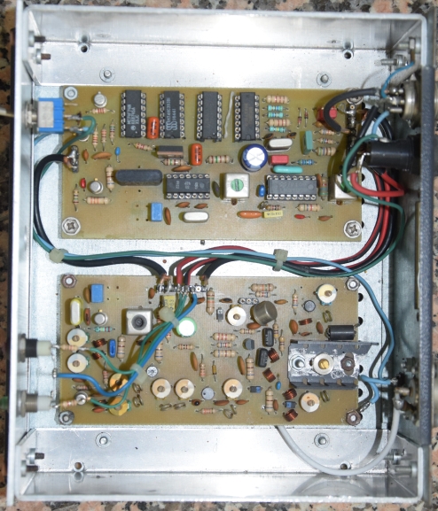
Here below, you can find a picture of IRBA equipment. I built all the equipments in the aluminum boxes 🙂

ir7ba

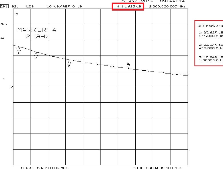
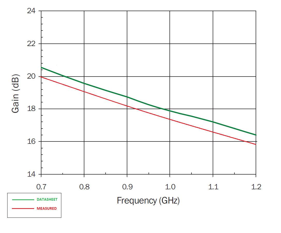
Being very proud of these first results, together with Fabio IW7DWL, I finalized the 1,2GHz radio. In those years, the RF instruments were very expensive and were difficult to find for a ham use. With courtesy of one my professors, I was able to use, only for few hours, the spectrum analyzer of my Technical School, and finally me and IW7DWL got our radios working. The link was established at few Kilometers, from me to Fabio’s house, but the link was good.

Here below, a picture of 23cm WBFM radio is reported:

dsc_0120.jpg

I was very satisfied, because in those years I was studying electronics and telecommunication at university, I could do practice on the hardware! I spent a lot of time and a lot of nights soldering, building and making tests in my lab.

In the 2003/2004, IR7BA was equipped with an internet connection and became an internet-gateway.

After some years of experiments with these radios, the Wi-Fi started to spread among the ham world, and the packet network was slowly upgraded with wifi links, especially the backbone links.

In the same years, together with Piero I7IGX, Nicola IK7SMY and Mauro IW7AVY, we developed a Bi-quad antenna for 2,4GHz and we enclosed a D-Link DWL-900AP+ access point in an outdoor box with a home-made power-over-ethernet system. Another important success was reached in 2003: the first local link upgraded to Wi-Fi!

Here below, some pictures of the home-made wifi outdoor box:

For furher details of the outdoor box project, see this website (italian, developed in 2003)

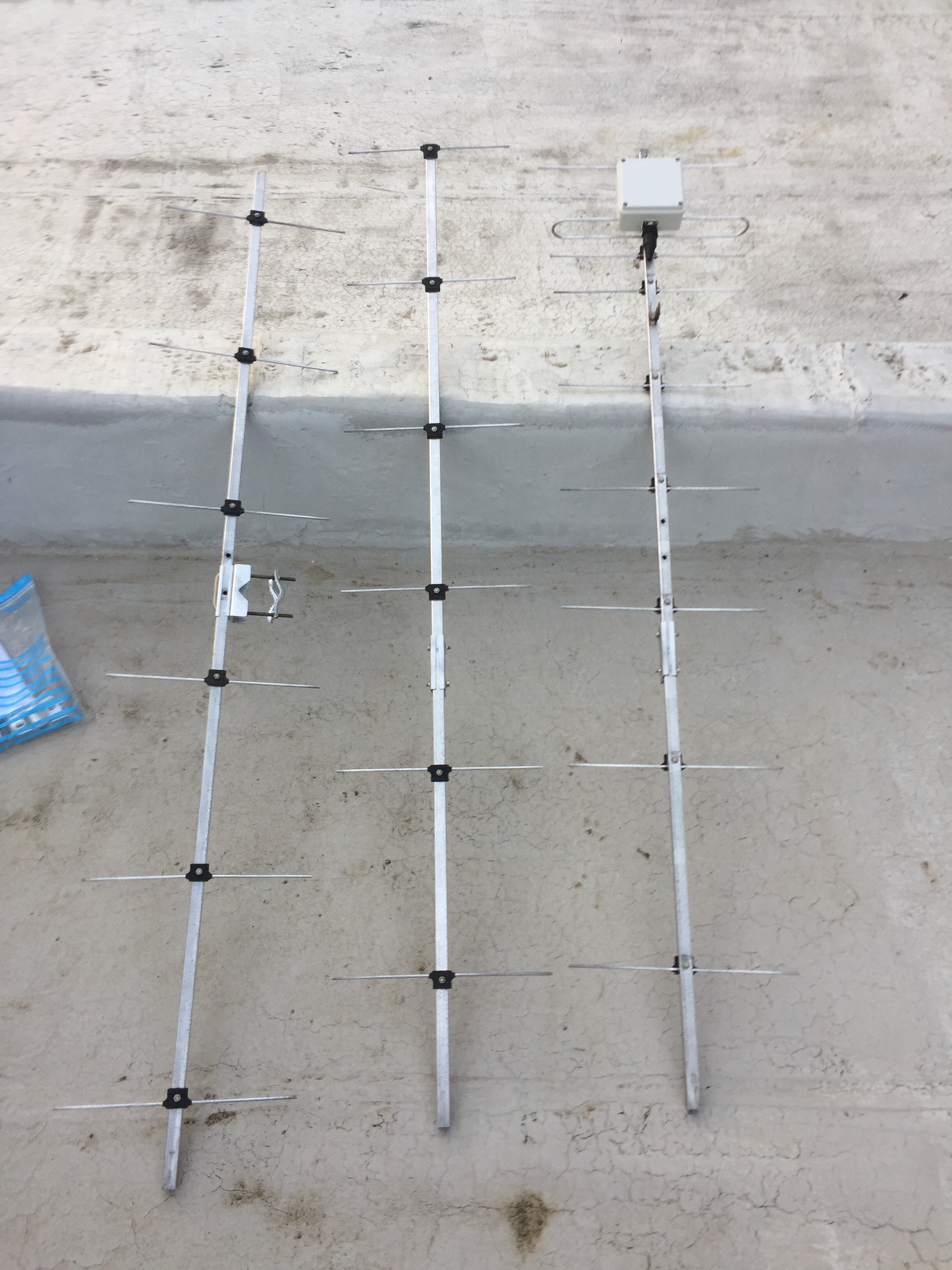
In the next years, other antennas were developed, built and installed on IR7BA: a vertical collinear, and a 3D-corner reflector, for longer links.

Here below, some pictures of 3D home-made corner reflector antenna (thanks to Mauro, IW7AVY for the nice manufacturing of copper parts):

In the next years, domestic access to internet became very fast and cheap, thanks to the ADSL connection. The interest for packet radio started to decrease and I had to move to Rome for work. IR7BA continued to live until 2010, when a thunderstorm and other technical problems on the equipment arised and there were not enough users to justify the effort for the system maintenance.

I continued my experiences with hamradio TCP-IP on 5,7GHz. I experimented mesh-networks and OLSRD protocol, joining ninux group (one of th world’s most active mesh neworks group) end applying hamradio IP numbering (44.x.x.x) on the nodes.

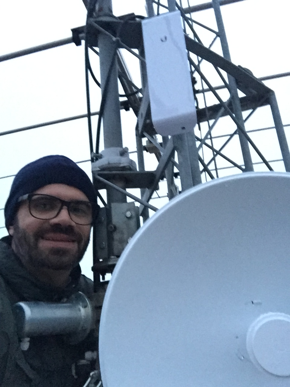
Here below, me after succesfully installing a Wifi link between me and IZ7YDL (about 20km distance):

wifi

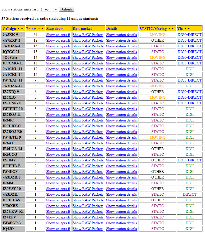
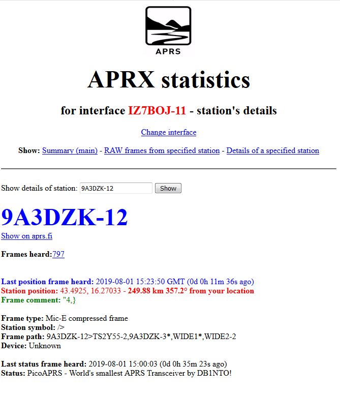
Nowadays, the packet radio is limited to aprs and other simple applications, but while I wrote this article I felt very nostalgic of this beautiful period of my life, when every information was not so easy so find because it was not ready on google, when it was necessary to keep in touch with other colleagues much more than today in order to increase the technical knowledge and to find solution to the technical problems, when I spent entire nights just to see packets decoded on my CRT screen and, yes..it had the taste of a fantastic conquest. yes, I know that I’m getting old 🙂

Alfredo IZ7BOJ

ESEO GNURadio decoder optimization — 7 February 2019

ESEO GNURadio decoder optimization

After the launch of ESEO, at the end of 2018, Daniel Estevez released his beautiful GNURadio decoder: https://destevez.net/2018/12/decoding-eseo/

I started to use it and tried to do some optimization.

After some hours spent in “trial and error” I’ve found this two tricks to improve the success of decoding satnogs recording files:

1) Decrease the “Multiply Const” from 1 to 0,7 (Daniel Estevez already talked about the big gain of satnogs recording)

2) Increase the cutoff frequency of Lowpass Filter from original 4,8KHz to 5,2KHz (sometimes 5,3KHz)

Moreover, Dr. Chris Bridges suggested me to add a HighPass filter with a cutoff-frequency of 50Hz.

Cattura

I tried this modifications with this satnogs observation: https://network.satnogs.org/observations/439335/ and the decoded packets increased from 235 (original configuration) to 322 .

I hope this suggestions can be useful to other people who want to use eseo decoder.

73’s

Alfredo IZ7BOJ