The flexibility and power of ARM series processors and Raspberries is well known, and the Raspberry PC is now increasingly popular in both the professional and amateur radio sectors.
For more than 10 years now, my I-Gate APRS has been running on this platform thanks to the well-known aprx software, without any stability problems (with UPS ,practically no reboot is necessary for entire months).
The use of cheap SDR dongles, such as the famous RTL-SDR, is widely used for decoding APRS traffic, so I also wanted to experiment with the use of this SDR on my node, and I must say that the sensitivity comparisons compared to Classic Radio System+TNC Hardware are amazing.
In parallel with the classic aprs on 144.800MHz at 1200baud, I started experimenting with the LoRa protocol in UHF. Precisely with the intention of maintaining the raspberry+aprx pair as the reference HW, I developed a KISS-TNC that allows Semtech LoRa modules to be interfaced with aprx via kiss-over-tcp protocol.
The Software is available at the following link: https://github.com/IZ7BOJ/RPi-LoRa-KISS-TNC-2ndgen .
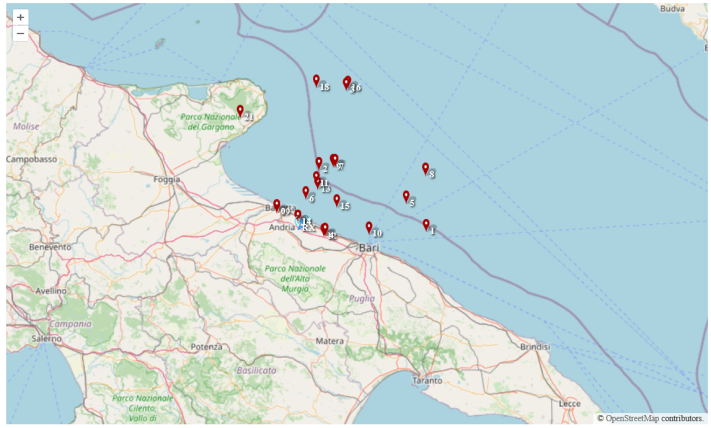
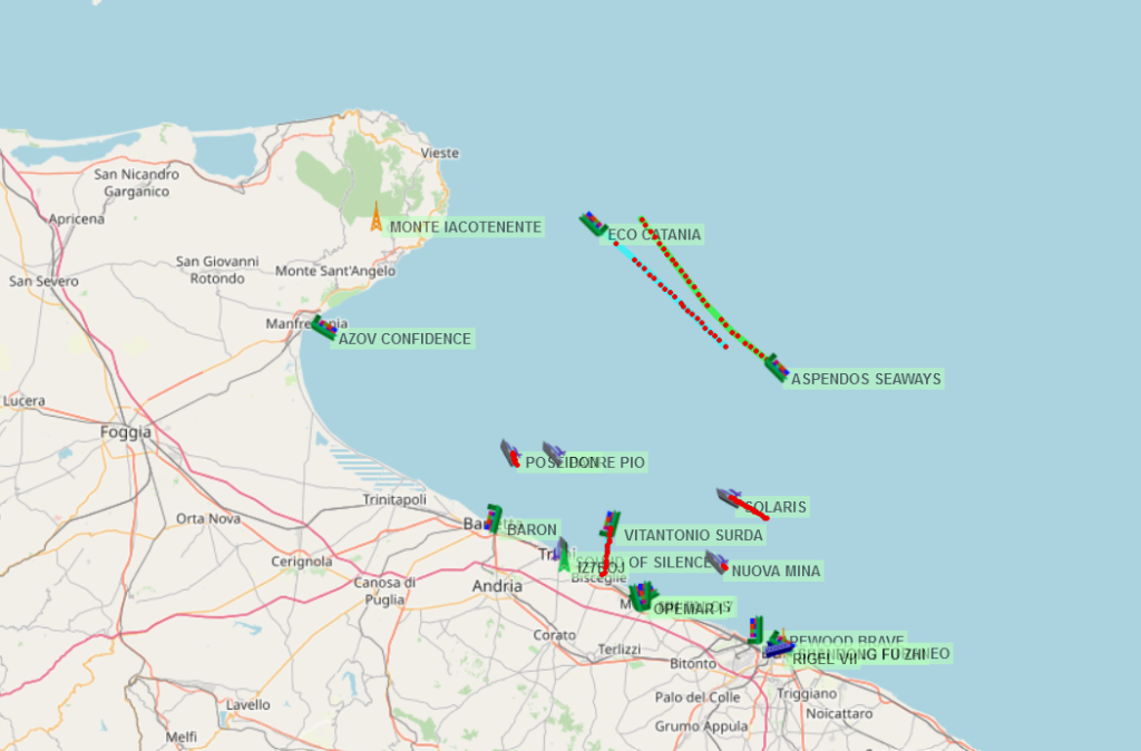
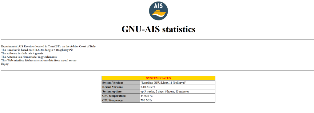
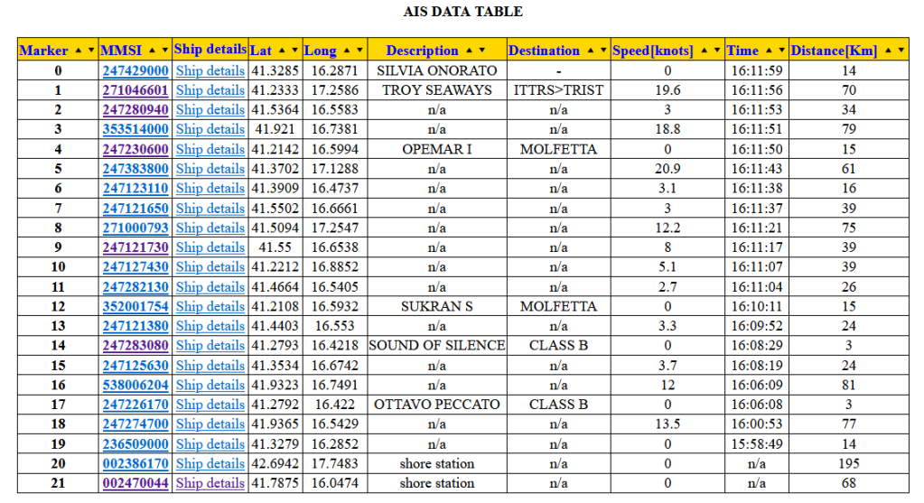
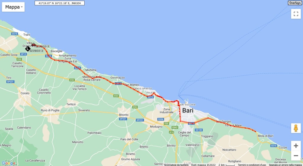
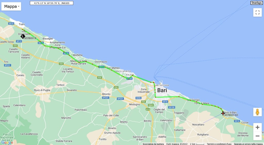
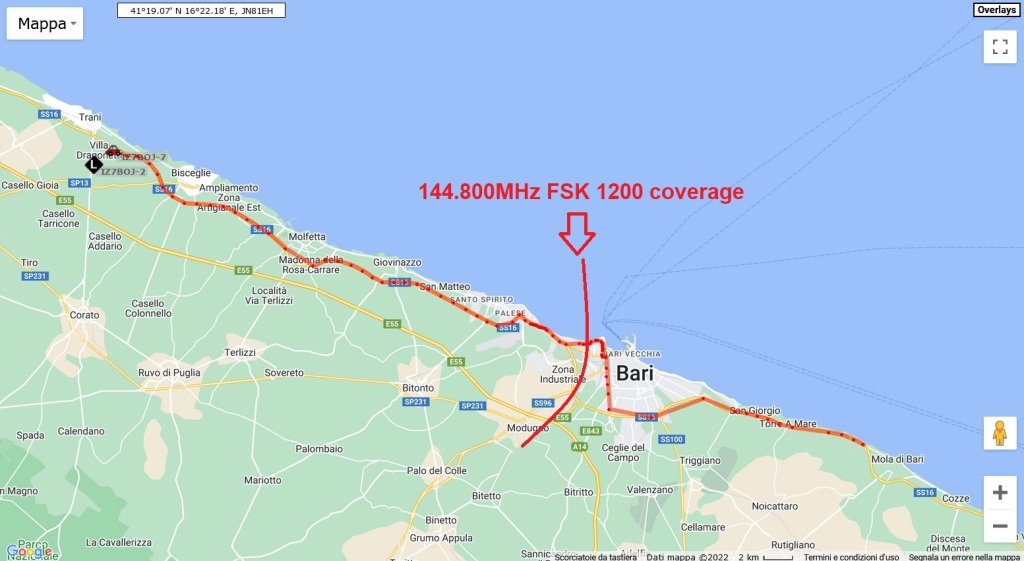
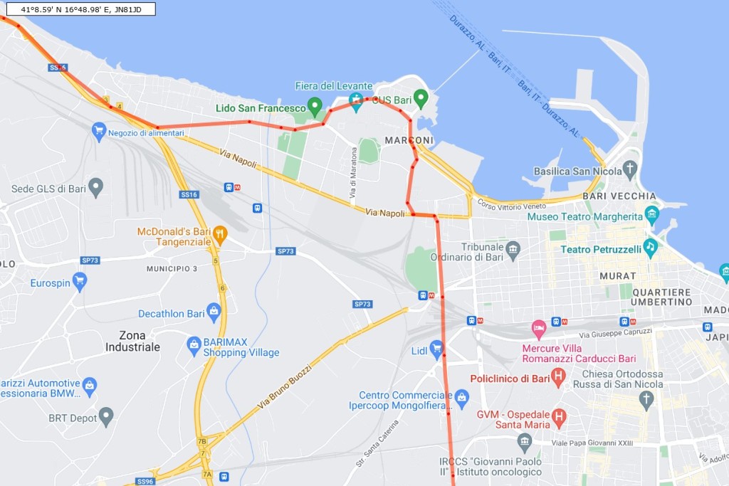
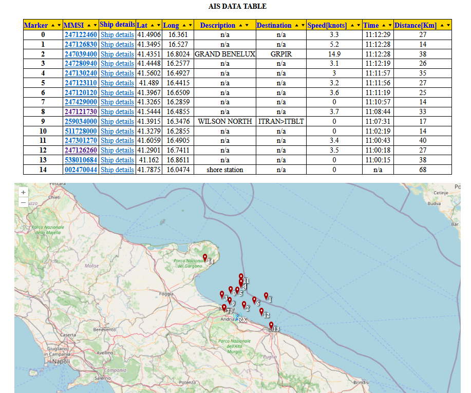
Still remaining in the field of geo-localization, I wanted to extend the experimentation to maritime traffic, so I implemented a gateway that transfers AIS traffic to the famous amateur portal aprs.fi.
Different software are ready to use in Windows and involve the use of a radio connected to the PC’s audio input, while in my implementation I used an SDR dongleand open-source applications described in this article.
To view local traffic both in a table and on a map, I developed a web dashboard, also described in the same article.
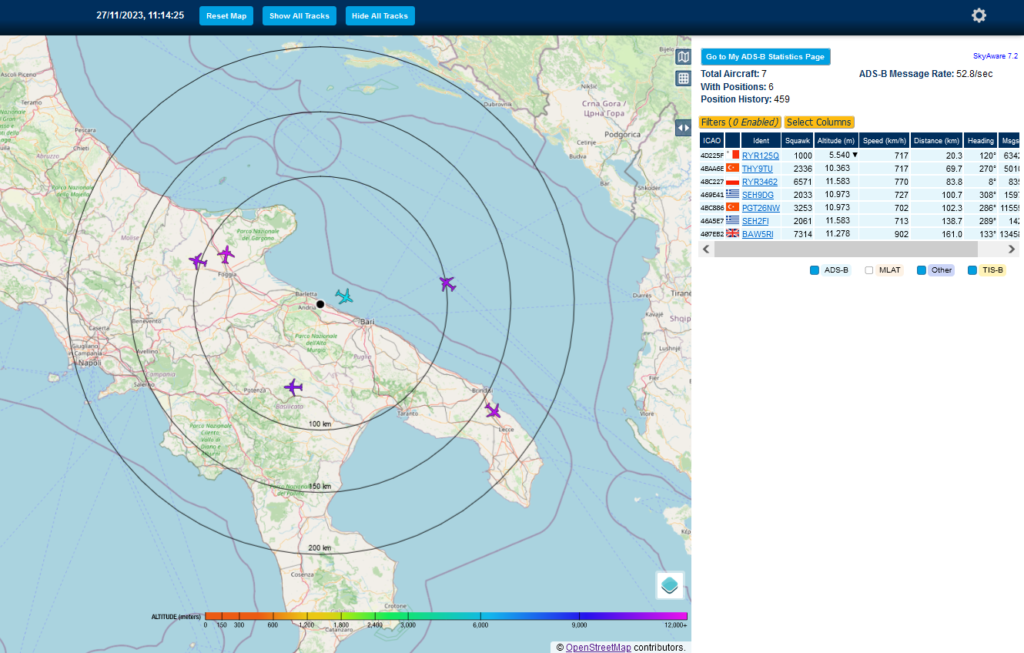
But if up to this point I have talked about ground stations and ships… at this point the only thing missing… is AIR! And so I added the third SDR stick dedicated to decoding ADS-B signals, the data of which is always available on the dashboard developed by Skyaware.
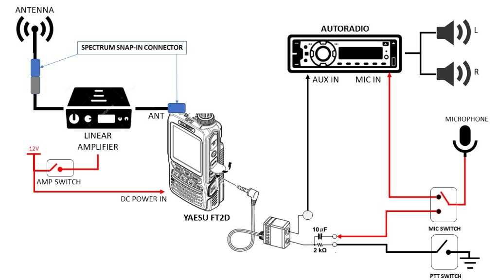
The block diagram of the node is available below, and I’m going to describe it afterwards.
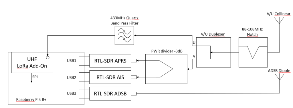
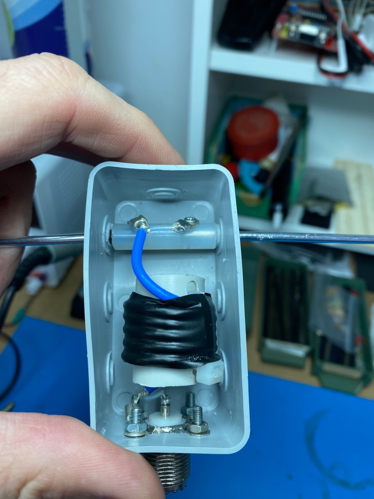
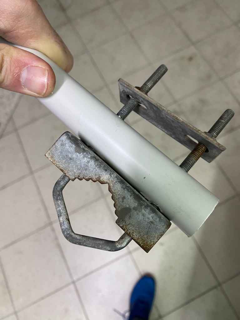
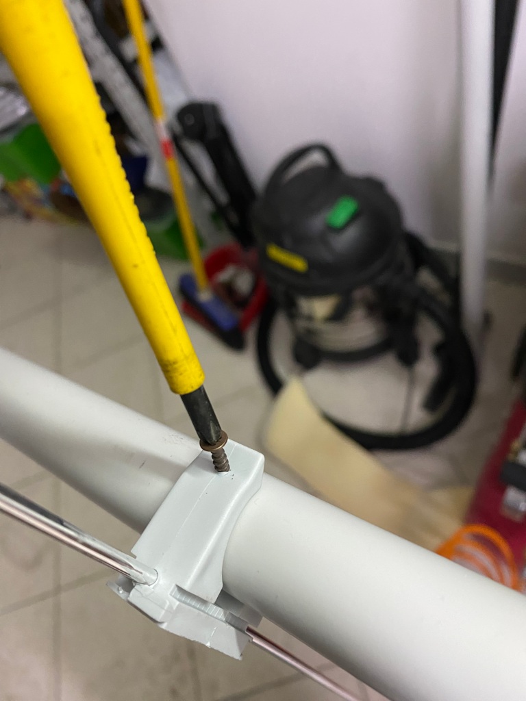
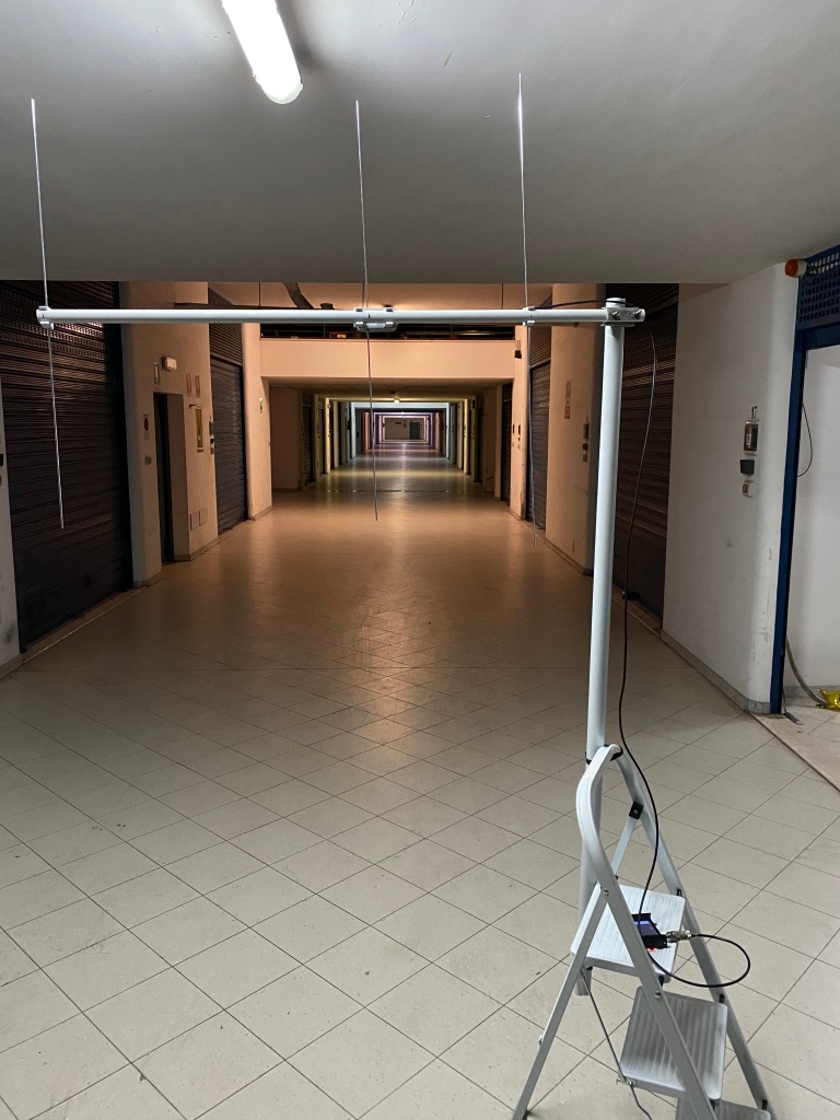
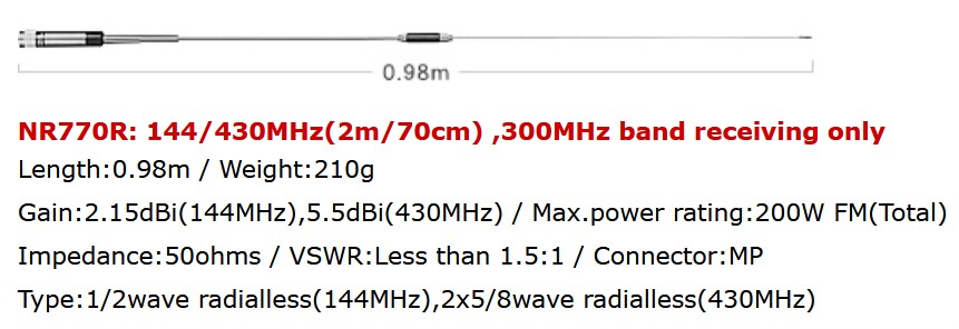
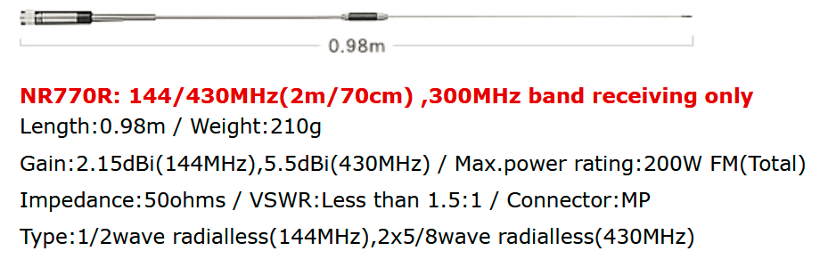
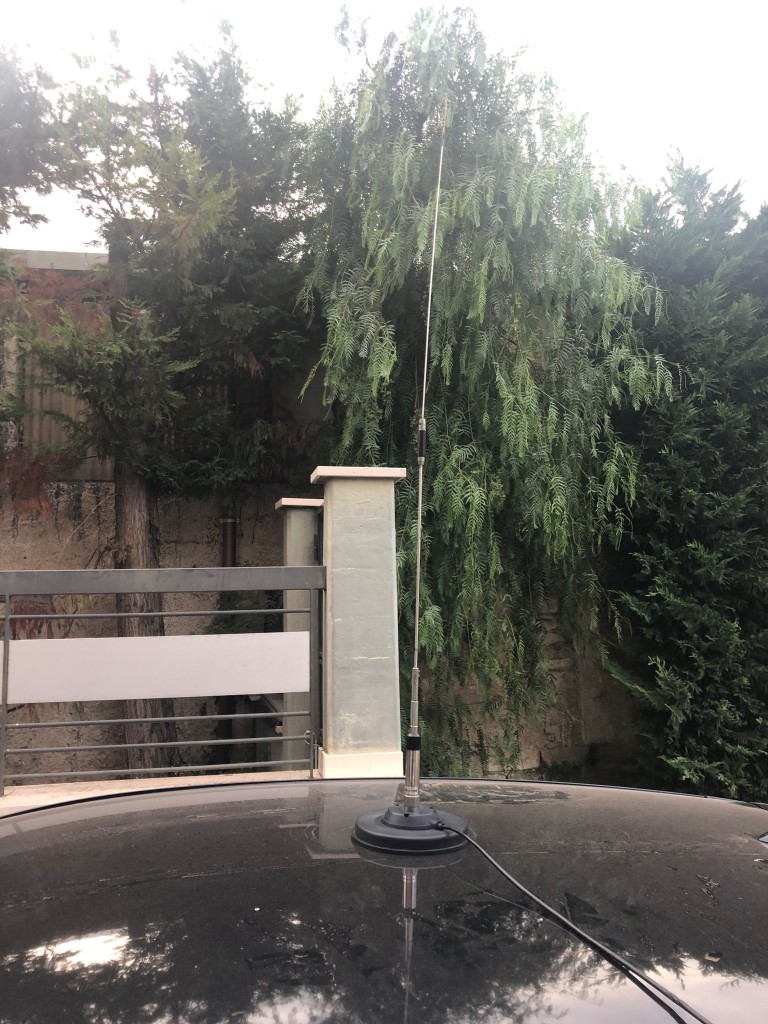
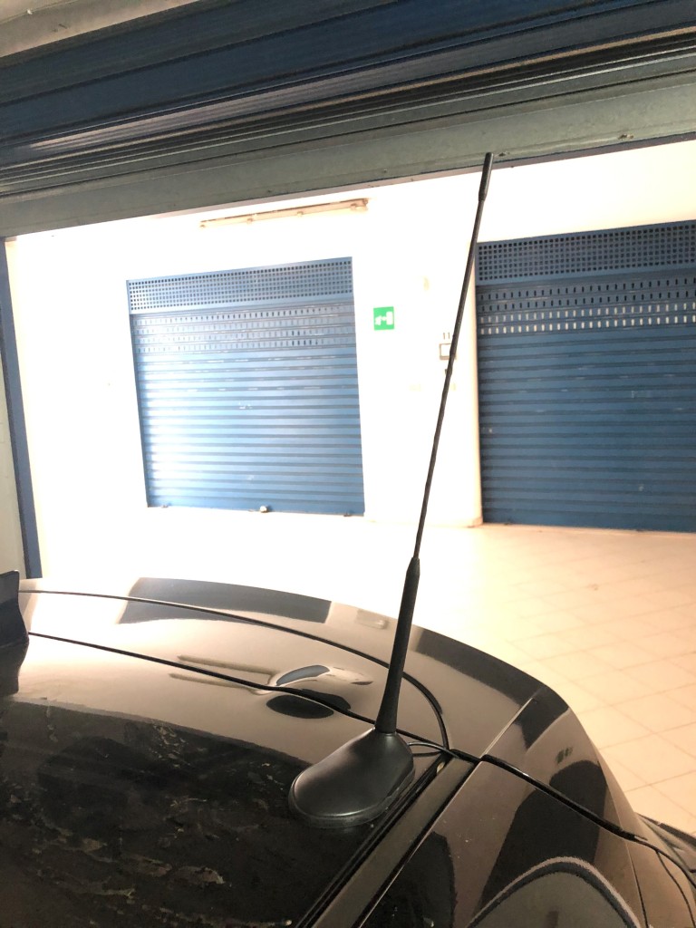
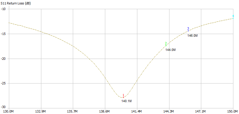
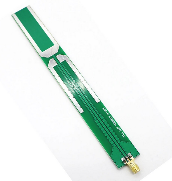
As is easy to see, the antennas in use are only a dual-band collinear and an antenna dedicated to ADS-B, bought for a few euros from Aliexpress and encapsulated in a 20mm PVC tube.
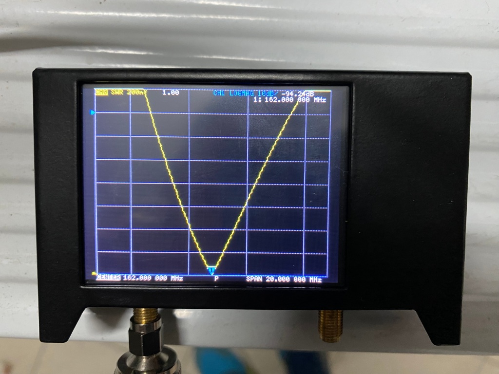
The signal coming from the collinear is first sent to a Notch filter which eliminates the 88-108MHz band of Broadcast FM broadcasters.
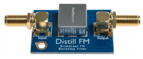
In fact, the RF front-end of the cheapest SDRs does not have any preselector filter, so they are desensitized in the presence of strong signals such as those of FM radios.
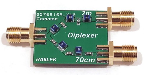
The output signal from the filter is then divided into VHF and UHF bands by a duplexer. For reasons of compactness and not having to manage large powers (the Lora module has only 1Watt output), I chose a mini V/U duplexer that uses SMD components, purchased from Ebay and built by the Hungarian Janilab.
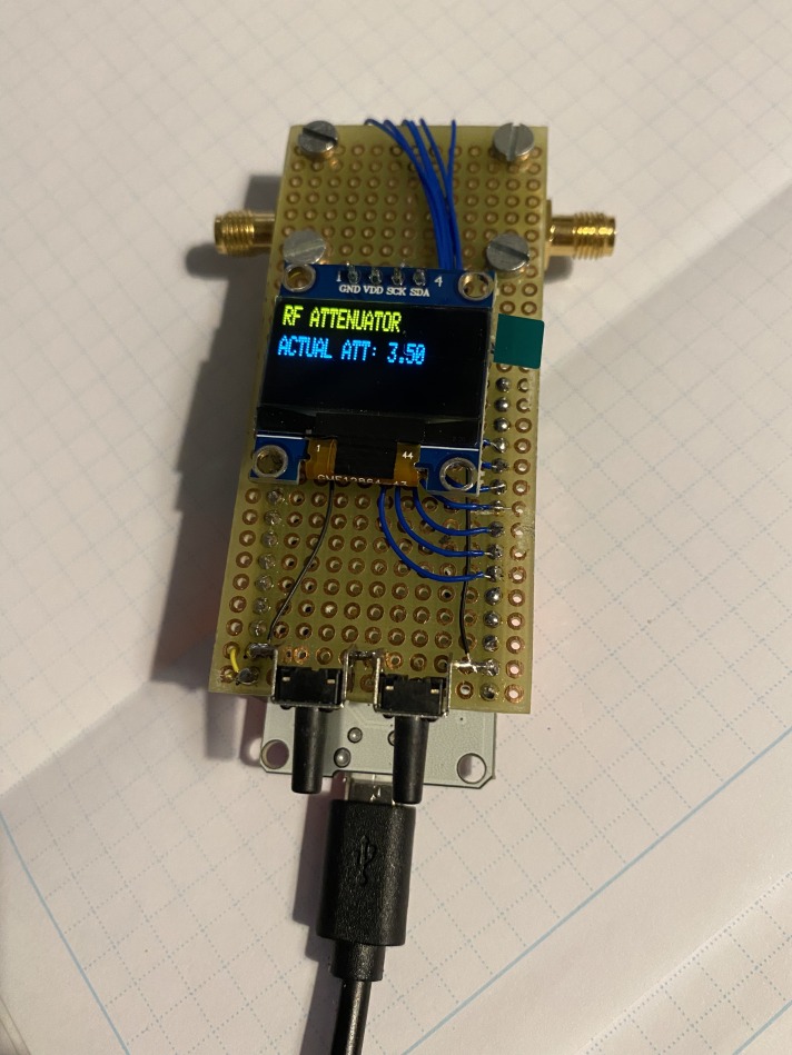
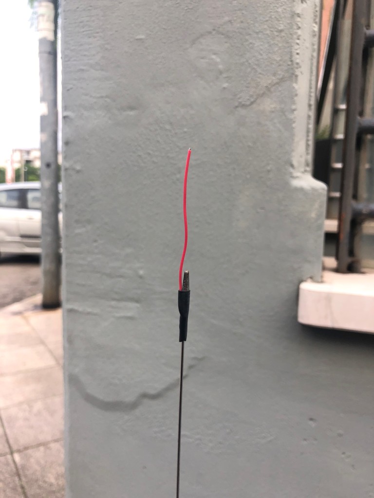
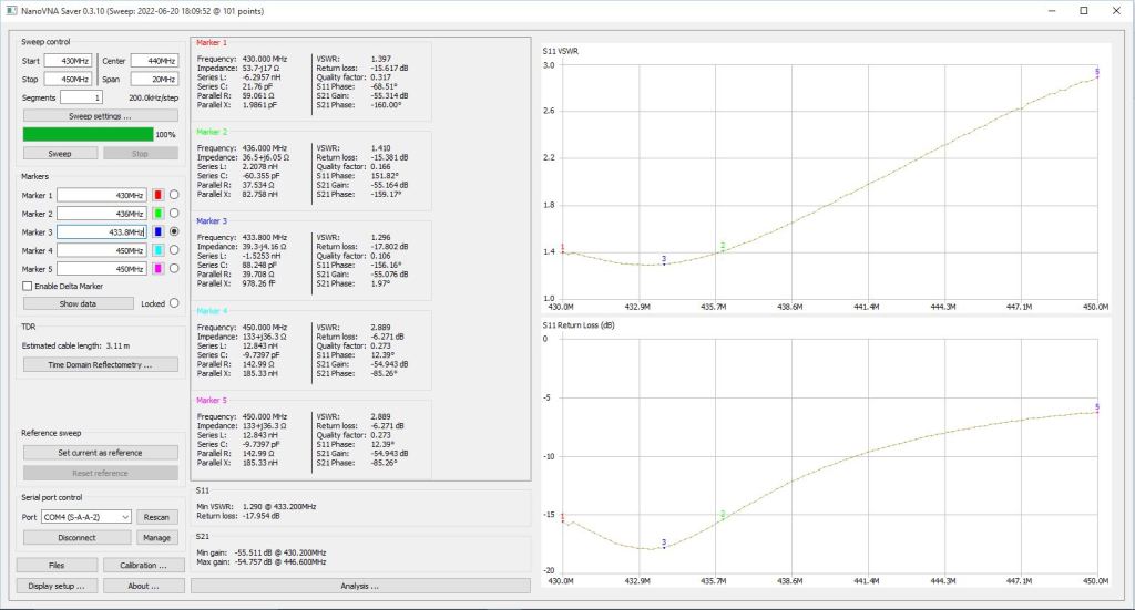
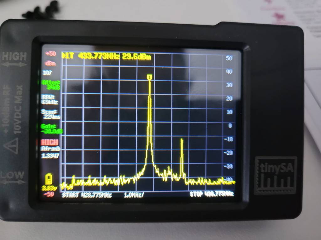
At this point the UHF signal is routed to the Lora module, first passing through a quartz filter calibrated at 433MHz, purchased from aliexpress.
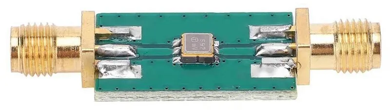
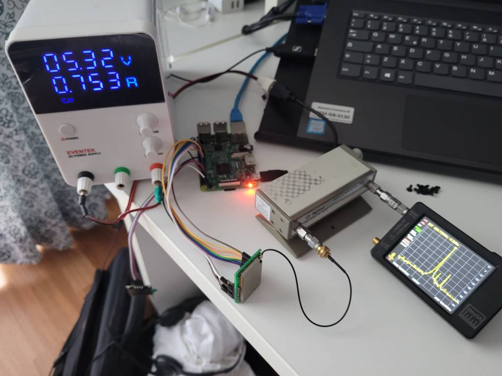
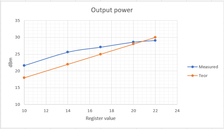
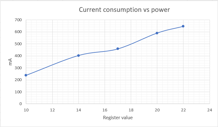
I wanted to try this filter because the front-end of the LoRa modules, especially the Ebyte E22-400M30S which has an LNA inside, does not have any filter at its input and therefore it is easy for it to saturate in the presence of strong signals in the UHF band .
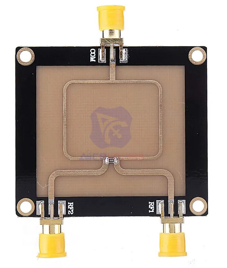
Since the 1200Baud APRS and the AIS signals both travel in the VHF band, although on slightly different frequencies, I used a power splitter easily available from Aliexpress to split the VHF signals between the SDR receivers dedicated to the aforementioned protocols.
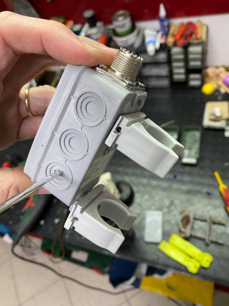
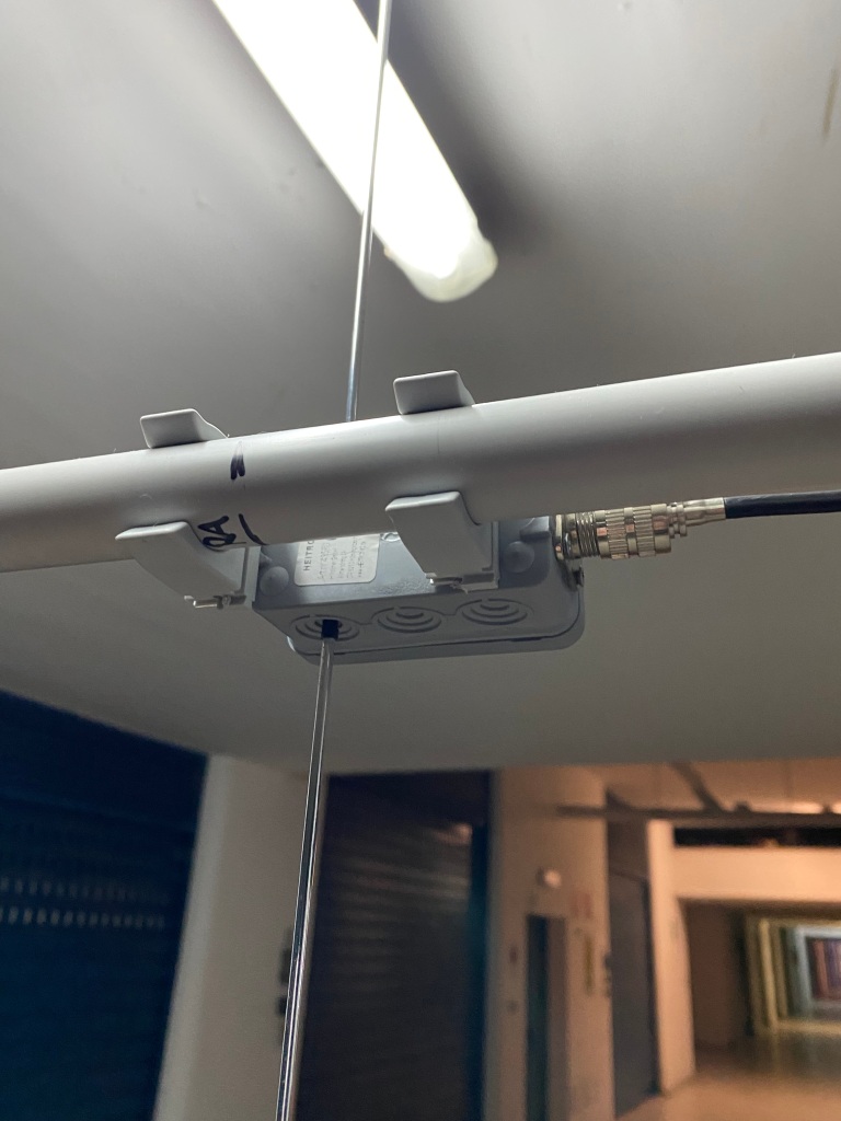
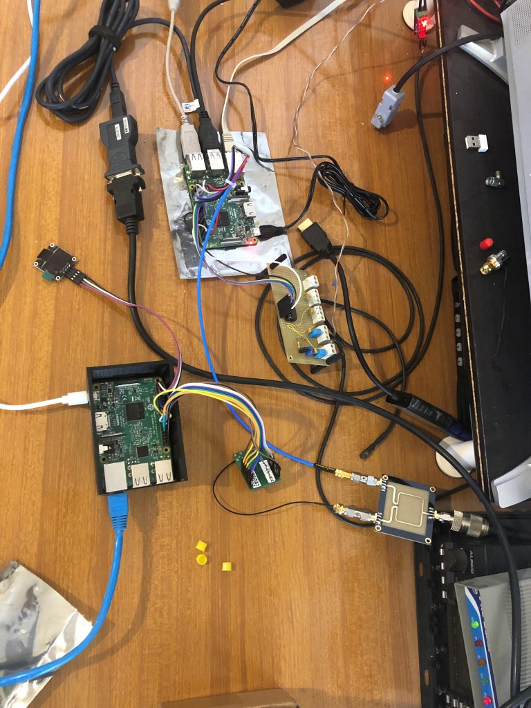
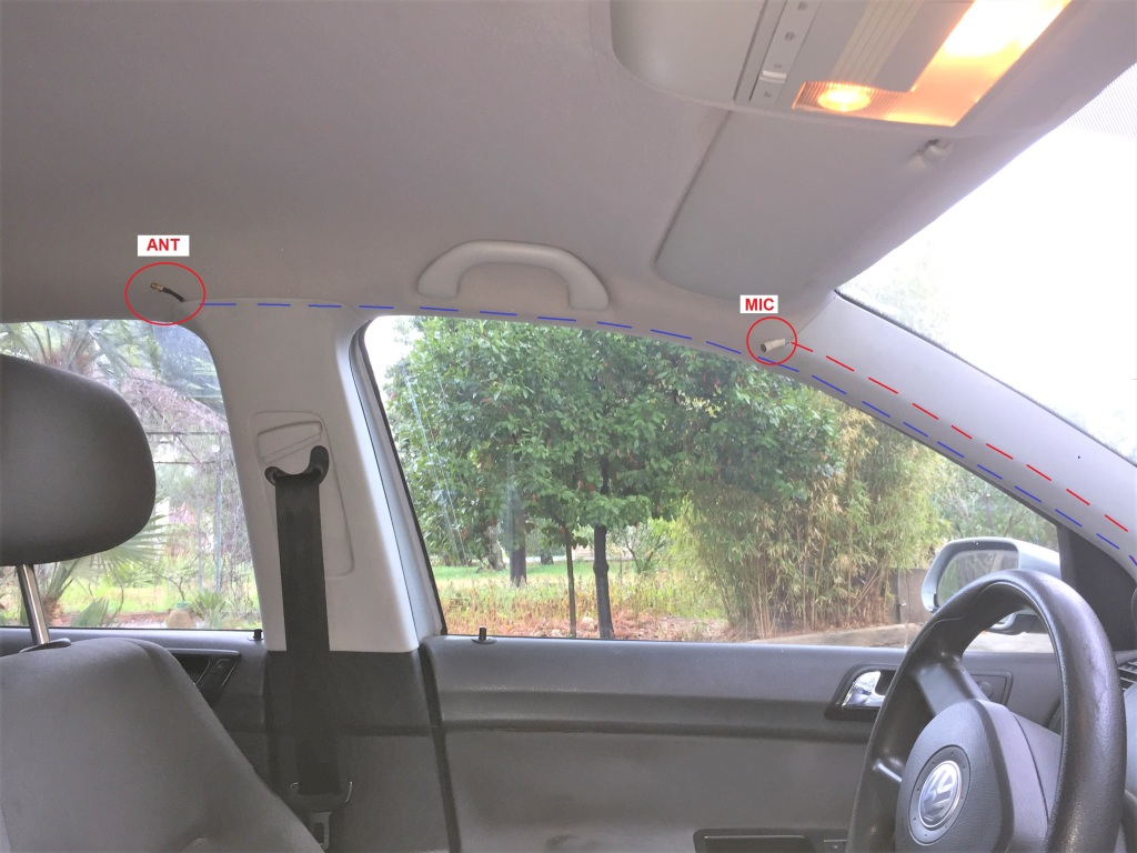
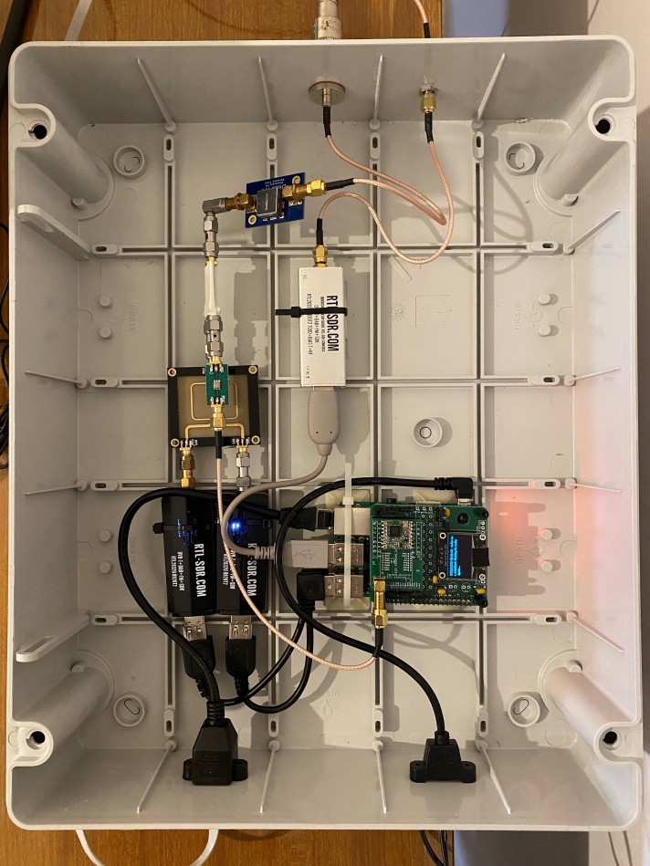
Below are some photos of the igate assembled inside a Gewiss 38x 30x 12cm box:
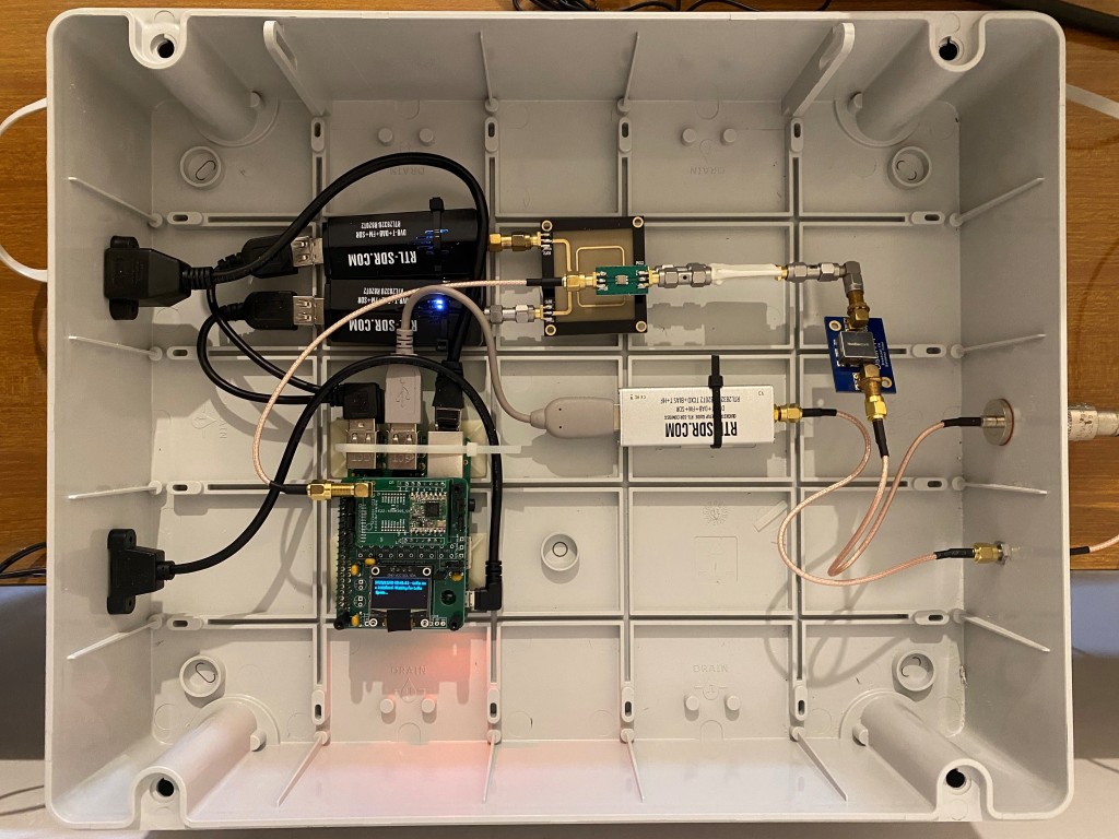
Here below, the same picture with indications of the building blocks:

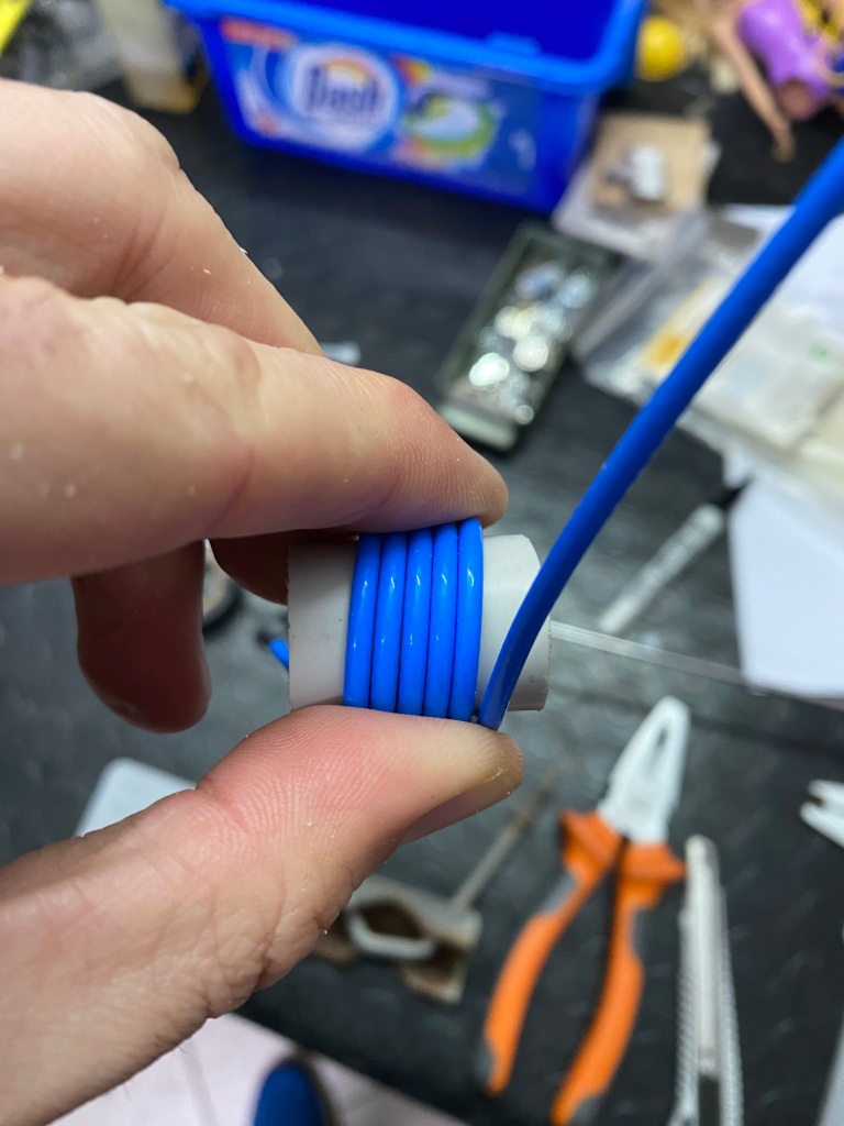
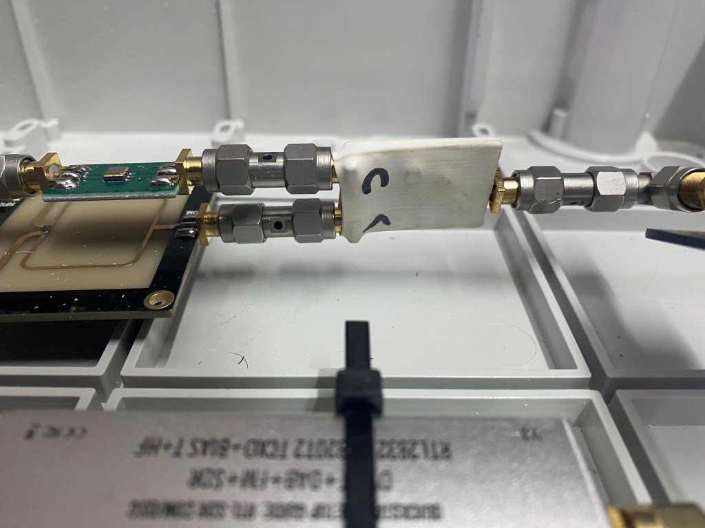
It’s worth to be noted that the diplexer is inside a white heat shrink tube:
So far the whole system has proven to be very stable and reliable, and the CPU load is under 50%, as can be seen by running the “top” command on the Raspberry:
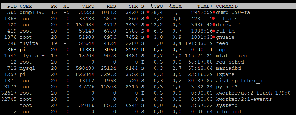
As you can see, the processes affected by aprs, ads-b and ais, highlighted by the red dot, use approximately 60% of the CPU.
Since there is still some power available, the next step will be to try adding a fourth satellite decoding stick 🙂
Ah, I forgot the most important thing: the igate homepage can be reached at http://iz7boj.dyndns.org/ . From it you can choose which dashboard to open and which information to view.
Hoping to have done something pleasant by sharing this experience, I greet all OM colleagues and wish you much fun!
Alfredo IZ7BOJ